Time Mark Products
-
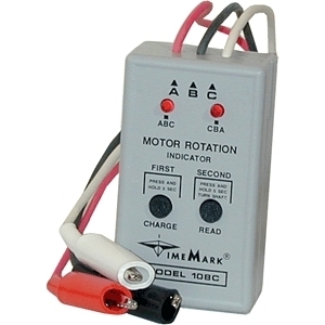
108C
Motor Rotation IndicatorSelect optionsRotating an electric motor shaft in the wrong direction can cause severe mechanical damage to expensive machinery. The Model 108C Motor Rotation Indicator can quickly show shaft rotation direction, thus becoming a valuable addition to your shop equipment. Designed of the installation of conveyer lines, pump systems and interconnected drives, the Model 108C requires only a few seconds to determine the proper connections to be made. The three leads are color coded: Red=phase A, Black=phase B, and White=phase C. This small device will allow you to connect all motors to run the proper direction.
-
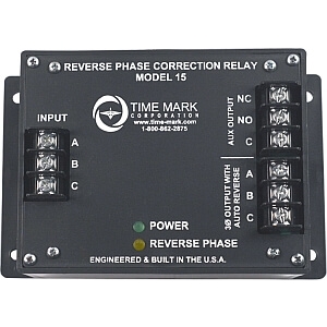
15-240
Reverse Phase RelaySelect optionsThe Time Mark Model 15 was designed to protect your valuable equipment from the damaging effects of phase reversal by sensing and automatically correcting for phase reversal. Under normal power conditions, incoming A B C voltage is passed straight through the device to the A B C output terminals (4 amps @ 480 VAC resistive max). If the unit detects an incoming reverse phase condition (C B A), it will light the reverse phase LED and internally switch 2 of the phases and then pass the corrected phasing out to output terminals A B C. If your load is higher than 4 amps @ 480VAC resistive, the Model 15 provides an auxiliary output relay to put in the control circuit of a remote reversing contactor. If phasing is correct, the relay will remain in the static condition (N.C contact will remain closed and N.O. will remain open). If the Model 15 detects a reverse phase input, the auxiliary output relay will energize and the relay contacts will switch (N.C contact will open and N.O. will close).
-
15-480
Reverse Phase RelaySelect optionsThe Time Mark Model 15 was designed to protect your valuable equipment from the damaging effects of phase reversal by sensing and automatically correcting for phase reversal. Under normal power conditions, incoming A B C voltage is passed straight through the device to the A B C output terminals (4 amps @ 480 VAC resistive max). If the unit detects an incoming reverse phase condition (C B A), it will light the reverse phase LED and internally switch 2 of the phases and then pass the corrected phasing out to output terminals A B C. If your load is higher than 4 amps @ 480VAC resistive, the Model 15 provides an auxiliary output relay to put in the control circuit of a remote reversing contactor. If phasing is correct, the relay will remain in the static condition (N.C contact will remain closed and N.O. will remain open). If the Model 15 detects a reverse phase input, the auxiliary output relay will energize and the relay contacts will switch (N.C contact will open and N.O. will close).
-
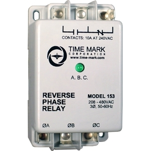
153
Reverse Phase RelaySelect optionsThe Model 153 Reverse Phase Relay is designed to continuously monitor phase rotation of 3-phase lines. This device should be used in applications where proper phase rotation is critical, such as fan motors, compressors, grinders, elevators, etc. The solid-state sensing circuit drives an internal electromechanical relay which energizes when power, with correct phase rotation, is applied. The relay will not energize if the applied phases are reversed. It will de-energize if phase rotation is reversed while the motor is running. An LED indicator will illuminate with correct ABC phase rotation.
-
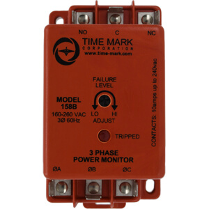
158B
3-Phase MonitorSelect optionsThe Model 158 continuously monitors 3-phase power lines for abnormal conditions. When properly adjusted, the Model 158 monitor will detect phase loss on a loaded motor even when regenerated voltage is present.
This device consists of a solid-state voltage and phase-angle sensing circuit, driving an electro-mechanical relay. When correct voltage and phase rotation are applied, the internal relay will energize. A fault condition will de-energize the relay. When the fault is corrected, the monitor will automatically reset.
The Model 158 does not require a neutral connection, and can be used with Wye or Delta systems. Four versions cover 120V, 208/240V, 480V (60Hz) and 380V (50Hz). Voltage ranges are sufficient to allow for proper adjustment to existing conditions. A front-mounted LED failure indicator is provided.
The R versions of the Model 158 monitor have an additional LED indicator for RESTART and a 5 minute short cycle timer, to delay restarting the motor.
-
158BR
3-Phase Monitor5 Min. Time DelaySelect optionsThe Model 158 continuously monitors 3-phase power lines for abnormal conditions. When properly adjusted, the Model 158 monitor will detect phase loss on a loaded motor even when regenerated voltage is present.
This device consists of a solid-state voltage and phase-angle sensing circuit, driving an electro-mechanical relay. When correct voltage and phase rotation are applied, the internal relay will energize. A fault condition will de-energize the relay. When the fault is corrected, the monitor will automatically reset.
The Model 158 does not require a neutral connection, and can be used with Wye or Delta systems. Four versions cover 120V, 208/240V, 480V (60Hz) and 380V (50Hz). Voltage ranges are sufficient to allow for proper adjustment to existing conditions. A front-mounted LED failure indicator is provided.
The R versions of the Model 158 monitor have an additional LED indicator for RESTART and a 5 minute short cycle timer, to delay restarting the motor.
-
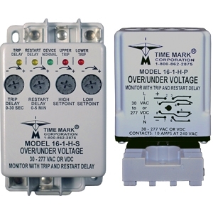
16-1-H-P
Over and/or Under Voltage MonitorSelect optionsThe Model 16-1-X-X protects equipment from Over, Under, Over/Under voltage or rapid cycling conditions that can damage valuable equipment. Trip and restart delays are adjustable, or can be disabled. Input voltage ranges are 12-30 VAC/VDC or 30-277 VAC/VDC. The 8-pin plug-in has 2 SPDT relays, while the surface mount case has 1 SPDT relay. See Ordering Information for details. 8-pin plug-in versions require an 8-pin socket, such as Time Mark’s Model 51X120. A proprietary microcontroller-based sensing circuit deenergizes the relay(s) after the trip delay (if enabled) upon detection of harmful voltage conditions. The relay(s) will energize after power line conditions return to an acceptable level and the restart delay time has expired (if enabled). Trip delays can be added to avoid nuisance tripping while restart delays can be used to stagger the startup of equipment or protect compressors. Time Mark’s proprietary microcontroller-based design offers maximum flexibility with an easy to use interface.
-
16-1-H-S
Over and/or Under Voltage MonitorSelect optionsThe Model 16-1-X-X protects equipment from Over, Under, Over/Under voltage or rapid cycling conditions that can damage valuable equipment. Trip and restart delays are adjustable, or can be disabled. Input voltage ranges are 12-30 VAC/VDC or 30-277 VAC/VDC. The 8-pin plug-in has 2 SPDT relays, while the surface mount case has 1 SPDT relay. See Ordering Information for details. 8-pin plug-in versions require an 8-pin socket, such as Time Mark’s Model 51X120. A proprietary microcontroller-based sensing circuit deenergizes the relay(s) after the trip delay (if enabled) upon detection of harmful voltage conditions. The relay(s) will energize after power line conditions return to an acceptable level and the restart delay time has expired (if enabled). Trip delays can be added to avoid nuisance tripping while restart delays can be used to stagger the startup of equipment or protect compressors. Time Mark’s proprietary microcontroller-based design offers maximum flexibility with an easy to use interface.
-
16-1-L-P
Over and/or Under Voltage MonitorSelect optionsThe Model 16-1-X-X protects equipment from Over, Under, Over/Under voltage or rapid cycling conditions that can damage valuable equipment. Trip and restart delays are adjustable, or can be disabled. Input voltage ranges are 12-30 VAC/VDC or 30-277 VAC/VDC. The 8-pin plug-in has 2 SPDT relays, while the surface mount case has 1 SPDT relay. See Ordering Information for details. 8-pin plug-in versions require an 8-pin socket, such as Time Mark’s Model 51X120. A proprietary microcontroller-based sensing circuit deenergizes the relay(s) after the trip delay (if enabled) upon detection of harmful voltage conditions. The relay(s) will energize after power line conditions return to an acceptable level and the restart delay time has expired (if enabled). Trip delays can be added to avoid nuisance tripping while restart delays can be used to stagger the startup of equipment or protect compressors. Time Mark’s proprietary microcontroller-based design offers maximum flexibility with an easy to use interface.
-
16-1-L-S
Over and/or Under Voltage MonitorSelect optionsThe Model 16-1-X-X protects equipment from Over, Under, Over/Under voltage or rapid cycling conditions that can damage valuable equipment. Trip and restart delays are adjustable, or can be disabled. Input voltage ranges are 12-30 VAC/VDC or 30-277 VAC/VDC. The 8-pin plug-in has 2 SPDT relays, while the surface mount case has 1 SPDT relay. See Ordering Information for details. 8-pin plug-in versions require an 8-pin socket, such as Time Mark’s Model 51X120. A proprietary microcontroller-based sensing circuit deenergizes the relay(s) after the trip delay (if enabled) upon detection of harmful voltage conditions. The relay(s) will energize after power line conditions return to an acceptable level and the restart delay time has expired (if enabled). Trip delays can be added to avoid nuisance tripping while restart delays can be used to stagger the startup of equipment or protect compressors. Time Mark’s proprietary microcontroller-based design offers maximum flexibility with an easy to use interface.
-
160B120
Over or Under Voltage MonitorSelect optionsThe Model 160B(R) Voltage Sensor is a single set-point voltage sensor. Input voltages above the set-point cause the output contacts to energize. Input voltages below the set-point cause the output contacts to de-energize. The dead band between pull-in and drop-out is less than 1%.
Wiring connections are made to 1/4 in.; quick connect terminals. Standard versions have a 2-second restart delay. The R versions of the Model 160B have a fixed 5-minute short cycle delay. The Model 160B has a screwdriver adjustable set-point range of approximately 35% of the maximum voltage. The unit can be factory calibrated to meet specific requirements.
AC versions of the Model 160B are not frequency sensitive and may be used in systems from 50 to 400 Hz. DC versions, or other short cycle periods, are available on request.
-
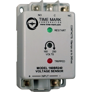
160B240
Over or Under Voltage MonitorSelect optionsThe Model 160B(R) Voltage Sensor is a single set-point voltage sensor. Input voltages above the set-point cause the output contacts to energize. Input voltages below the set-point cause the output contacts to de-energize. The dead band between pull-in and drop-out is less than 1%.
Wiring connections are made to 1/4 in.; quick connect terminals. Standard versions have a 2-second restart delay. The R versions of the Model 160B have a fixed 5-minute short cycle delay. The Model 160B has a screwdriver adjustable set-point range of approximately 35% of the maximum voltage. The unit can be factory calibrated to meet specific requirements.
AC versions of the Model 160B are not frequency sensitive and may be used in systems from 50 to 400 Hz. DC versions, or other short cycle periods, are available on request.