-
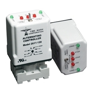
2611-120
Alternating ControllerSelect optionsModel 2611 Alternating Controllers are microprocessor-based designs for use where two loads are required to alternate for equal run time. LED indicators show status of the units three contact switch inputs and two load outputs. The controllers lead select switch allows loads to alternate normally in the center position, or disable automatic sequencing and lock in a 1-2 or 2-1 sequence. When a Stop, Lead, or Lag switch closes – corresponding LED atop the Model 2611 illuminates.
-
2611-24
Alternating ControllerSelect optionsModel 2611 Alternating Controllers are microprocessor-based designs for use where two loads are required to alternate for equal run time. LED indicators show status of the units three contact switch inputs and two load outputs. The controllers lead select switch allows loads to alternate normally in the center position, or disable automatic sequencing and lock in a 1-2 or 2-1 sequence. When a Stop, Lead, or Lag switch closes – corresponding LED atop the Model 2611 illuminates.
-
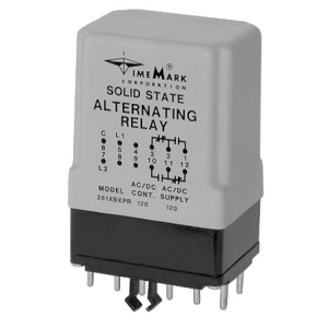
261XBXP-120
Alternating RelaySelect optionsThe Model 261XBXP(R) Alternating Relay uses the same solid-state latching and control circuit as all the other 261 series models, the enclosure and the connecting base being the major differences. This version was designed to replace a long time and widely used mechanical latching relay offered by another manufacturer. The modern circuitry used the Model 261XBXP offers a vast improvement in reliability and useful life over the mechanical type. The XBXP version of the relay requires closing the control switch to begin alternation, and the XBXPR version requires opening the control switch to begin alternation. Replacement of the original mechanical alternator with the Model 261XBXP requires the addition of wire from L1 to Pin 5 of the connector in order to supply continuous power to the solid-state circuit. Available in two voltage versions for use with 24 VAC/DC or 120 VAC/DC.
-
261XBXP-24
Alternating RelaySelect optionsThe Model 261XBXP(R) Alternating Relay uses the same solid-state latching and control circuit as all the other 261 series models, the enclosure and the connecting base being the major differences. This version was designed to replace a long time and widely used mechanical latching relay offered by another manufacturer. The modern circuitry used the Model 261XBXP offers a vast improvement in reliability and useful life over the mechanical type. The XBXP version of the relay requires closing the control switch to begin alternation, and the XBXPR version requires opening the control switch to begin alternation. Replacement of the original mechanical alternator with the Model 261XBXP requires the addition of wire from L1 to Pin 5 of the connector in order to supply continuous power to the solid-state circuit. Available in two voltage versions for use with 24 VAC/DC or 120 VAC/DC.
-
261XBXPR-120
Alternating RelaySelect optionsThe Model 261XBXP(R) Alternating Relay uses the same solid-state latching and control circuit as all the other 261 series models, the enclosure and the connecting base being the major differences. This version was designed to replace a long time and widely used mechanical latching relay offered by another manufacturer. The modern circuitry used the Model 261XBXP offers a vast improvement in reliability and useful life over the mechanical type. The XBXP version of the relay requires closing the control switch to begin alternation, and the XBXPR version requires opening the control switch to begin alternation. Replacement of the original mechanical alternator with the Model 261XBXP requires the addition of wire from L1 to Pin 5 of the connector in order to supply continuous power to the solid-state circuit.
Available in two voltage versions for use with 24 VAC/DC or 120 VAC/DC.
-
261XBXPR-24
Alternating RelaySelect optionsThe Model 261XBXP(R) Alternating Relay uses the same solid-state latching and control circuit as all the other 261 series models, the enclosure and the connecting base being the major differences. This version was designed to replace a long time and widely used mechanical latching relay offered by another manufacturer. The modern circuitry used the Model 261XBXP offers a vast improvement in reliability and useful life over the mechanical type. The XBXP version of the relay requires closing the control switch to begin alternation, and the XBXPR version requires opening the control switch to begin alternation. Replacement of the original mechanical alternator with the Model 261XBXP requires the addition of wire from L1 to Pin 5 of the connector in order to supply continuous power to the solid-state circuit.
Available in two voltage versions for use with 24 VAC/DC or 120 VAC/DC.
-
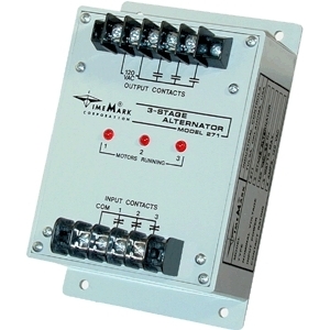
271
3-Stage AlternatorSelect optionsThe Model 271 3-Stage Alternator is designed to control the motor starters in a stage pumping or compressor system. Its purpose is to ensure that only the required motors are used, and that each motor receives the same average amount of run time. Motors are sequenced in a first-on, first-off cycle. Potential uses include water supply systems, air compressor systems, sewage disposal plant systems, storage tank filling or emptying systems, water recycling systems, irrigation systems or sump pump applications.
-
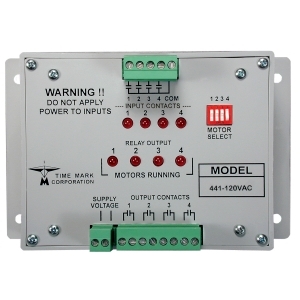
441-120
Multi-Stage AlternatorSelect optionsThe Model 441 Multi-Stage Alternator is designed to control the operating sequence of multi-stage motor/pumping systems. It can also be used to maintain the desired level of pressure-on air compressor systems. Four motor select DIP switches located on the front panel allow the alternator to control a single-motor/pump, two-motor/pump, three-motor/pump or four-motor/pump system. The Model 441 will assure that only the necessary motors/pumps are operating, and that the run time for each motor/pump is approximately equal. Motors are sequenced first-on, first-off. If the motor/pumping demand requires only one motor/pump at a time, the alternator will start the next motor/pump in sequence each time an input switch is closed. Input switches may be float switches, pressure switches, flow switches, etc. , as required by the application.
Potential uses for the Model 441 include water supply systems, sewage disposal plant systems, storage tank filling systems, air compressor systems, irrigation and water recycling systems.
-
441-240
Multi-Stage AlternatorSelect optionsThe Model 441 Multi-Stage Alternator is designed to control the operating sequence of multi-stage motor/pumping systems. It can also be used to maintain the desired level of pressure-on air compressor systems. Four motor select DIP switches located on the front panel allow the alternator to control a single-motor/pump, two-motor/pump, three-motor/pump or four-motor/pump system. The Model 441 will assure that only the necessary motors/pumps are operating, and that the run time for each motor/pump is approximately equal. Motors are sequenced first-on, first-off. If the motor/pumping demand requires only one motor/pump at a time, the alternator will start the next motor/pump in sequence each time an input switch is closed. Input switches may be float switches, pressure switches, flow switches, etc. , as required by the application.
Potential uses for the Model 441 include water supply systems, sewage disposal plant systems, storage tank filling systems, air compressor systems, irrigation and water recycling systems.
-
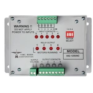
442-120
Multi-Stage AlternatorSelect optionsThe Model 442 Multi-Stage Alternator is designed to control the operating sequence of multi-stage motor/pumping systems. It can also be used to maintain the desired level of pressure-on air compressor systems. Four motor select DIP switches located on the front panel allow the alternator to control a single-motor/pump, two-motor/pump, three-motor/pump or four-motor/pump system. The Model 442 will assure that only the necessary motors/pumps are operating, and that the run time for each motor/pump is approximately equal. Motors are sequenced Sequence-On, Simultaneous-Off . If the motor/pumping demand requires only one motor/pump at a time, the alternator will start the next motor/pump in sequence each time an input switch is closed. Input switches may be float switches, pressure switches, flow switches, etc. , as required by the application.
Potential uses for the Model 442 include water supply systems, sewage disposal plant systems, storage tank filling systems, air compressor systems, irrigation and water recycling systems.
-
442-240
Multi-Stage AlternatorSelect optionsThe Model 442 Multi-Stage Alternator is designed to control the operating sequence of multi-stage motor/pumping systems. It can also be used to maintain the desired level of pressure-on air compressor systems. Four motor select DIP switches located on the front panel allow the alternator to control a single-motor/pump, two-motor/pump, three-motor/pump or four-motor/pump system. The Model 442 will assure that only the necessary motors/pumps are operating, and that the run time for each motor/pump is approximately equal. Motors are sequenced Sequence-On, Simultaneous-Off . If the motor/pumping demand requires only one motor/pump at a time, the alternator will start the next motor/pump in sequence each time an input switch is closed. Input switches may be float switches, pressure switches, flow switches, etc. , as required by the application.
Potential uses for the Model 442 include water supply systems, sewage disposal plant systems, storage tank filling systems, air compressor systems, irrigation and water recycling systems.
-
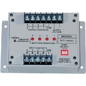
A471
Multi-Stage AlternatorSelect optionsThe Model 471 Multi-Stage Alternator is designed to control the operating sequence of multi-stage pumping systems. it can also be used to maintain the desired level of pressure on air compressor systems. Four PUMP SELECT DIP switches located on the front panel allow the alternator to control a single-pump, two-pump, three-pump or four-pump system. Only one switch needs to be set for the total number of pumps in the system. The Model 471 will assure that only the necessary pumps are operating, and that the run time for each pump is approximately equal. Pumps are sequenced first-on and first-off. If the pumping demand requires only one pump at a time, the alternator will start the next pump in sequence each time an input switch is closed. Input switches may be float switches, pressure switches, flow switches, etc. , as required by the application.
Potential uses for the Model 471 include water supply systems, sewage disposal plant systems, storage tank filling systems, air compressor systems, irrigation and water recycling systems.
![]() Engineered and Built in the USA
Engineered and Built in the USA
Alternating Relays
Below you'll find a list of all items that have been categorized as “Alternating-Relays”