-
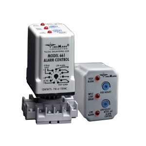
661
Alarm ControlSelect optionsThe Model 661 Alarm Control, part of the 600 series line of instrumentation controls, is designed to monitor and maintain measurable applications such as liquid levels, temperature, pressure, flow, etc. A user-provided 4-20mA current loop represents the measurable application, and output connections are provided for signal alarms. Two setpoints, the HIGH ADJUST, and the LOW ADJUST, are field adjustable. If the input is between the two setpoints, the relays are energized. If the input is above the high setpoint, the HIGH ALARM relay de-energizes to provide a tripped condition. This tripped condition will automatically reset when the input falls back below the setpoint. If the input falls below the low setpoint the LOW ALARM relay de-energizes. The tripped condition resets when the input rises back above the setpoint.
The Model 661 is equipped with top-mounted LEDs for trip status indication. A HIGH ALARM or LOW ALARM LED turns OFF in a tripped condition. The INPUT LOOP ERROR LED turns ON if the input is outside the 4-20mA range. A Time Mark Model 650 Loop Power Supply (or equivalent) is required to provide DC operating voltage. A Time Mark Model 672-15 Pressure Transducer (or equivalent) is required to provide the input signal.
-
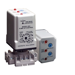
662
Pump Up ControlSelect optionsThe Model 662 Pump Up Control, part of the 600 series line of instrumentation controls, is designed to monitor andmaintain liquid levels. A user-provided 4-20mA current loop represents the liquid level, and output connections are provided for pump control. The HIGH ADJUSTsetpoint, and the LOW ADJUST setpoint, are field adjustable. If the input falls below the low setpoint, the PUMP UP relay energizes, and remains that way until the input rises above the high setpoint. The high setpoint must always be set above the low setpoint. Top-mounted LEDs on the Model 662 show system status. The PUMP UP LED turns ON when the input falls to 10% below the low setpoint, and resets when the input rises above this level. An INPUT LOOP ERROR LED turns ON if the input is outside the 4-20mA range. A Time Mark Model 650 Loop Power Supply (or equivalent) is required to provide the 24 VDC operating voltage.
A Time Mark Model 672-15 Pressure Transducer (or equivalent) is required to provide the input signal.
-
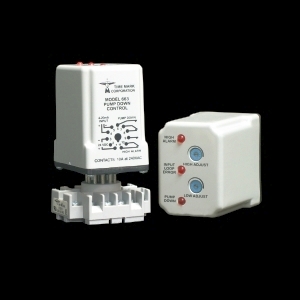
663
Pump Down ControlSelect optionsThe Model 663 Pump Down Control, part of the 600 series line of instrumentation controls, is designed to monitor and maintain liquid levels. A user-provided 4-20mA current loop represents the liquid level. The HIGH ADJUST setpoint, and the LOW ADJUST setpoint, are field adjustable. If the input rises above the high setpoint, the PUMP DOWN relay energizes, and remains that way until the input falls below the low set point. Top-mounted LEDs on the Model 663 show system status. The PUMP DOWN LED turns ON when the input is above the high setpoint, and goes OFF when the input is below the low setpoint. The HIGH ALARM condition indicator turns ON if the input rises to 10% above the high setpoint. The HIGH ALARM condition then resets when the input is again less than 10% above the high setpoint. For proper operation, the high setpoint must always be set above the low setpoint. An INPUT LOOP ERROR LED turns ON if the input is outside the 4-20mA range. A Time Mark Model 650 Loop Power Supply (or equivalent) is required to provide the 24 VDC operating voltage. Also, a Time Mark Model 672-15 Pressure Transducer (or equivalent) is required to provide the input signal.
-
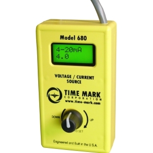
680
Voltage/Current SimulatorSelect optionsThe Model 680 is a user selectable voltage or current simulator. It is useful for the setup and testing of process controllers and indicators with either a current loop or control voltage input, such as liquid level controllers and other devices. The mode of operation is displayed on the top line of the LCD. Either 4-20mA, 0-20mA, 0-10V, or 0-5V. The Model 680 can be set to any one of these four modes of operation by holding down the rotary push-button until the desired mode is displayed. The mode is saved in nonvolatile memory so that the device will power up in the mode last selected. The output signal level is displayed on the bottom line of the LCD. On power up or on changing the mode of operation, the output goes to the range minimum, i. e. 4mA, 0mA, or 0V. The Model 680 offers short circuit protection by actively sensing for any overload condition and limiting output current to 20mA. Overload at the output is indicated by OL on the top line of the LCD and occurs when the output current is 21mA or greater. Signal level is adjustable with the rotary dial in increments of 0.1mA or 0.1V, or you can depress the dial to quickly jump between the minimum and maximum values of the range.
-
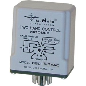
850-120VAC
Two Hand Control Module120 VACSelect optionsThe Model 850 Two Hand Control Module is designed to be used with two palm or push-button switches, which must be closed within 0.5 seconds of each other to operate machinery. As long as both switches are pressed, the relay will remain energized in the continuous mode. For applications requiring a pulse to initiate operations, the Model 850 can be set to produce a pulse output by connecting a resistor to pins 4 and 7. The resistor value in ohms should be 100,000 times the desired time in seconds (R=100,000 x T). The internal relay de-energizes on completion of the pulse, even if both switches are depressed. The relay also will de-energize immediately, if either hand switch is released, in standard or pulsed mode. The compact size of the Two-Hand Control Module allows installation into an existing control panel. It can be used with any type of machinery requiring safe, two-handed operation such as presses, punches, cutters, etc. The standard nominal supply voltages are 120VAC, 240VAC, or 24VAC at 50/60 Hz. , or 24VDC.
-
850-240VAC
Two Hand Control Module240 VACSelect optionsThe Model 850 Two Hand Control Module is designed to be used with two palm or push-button switches, which must be closed within 0.5 seconds of each other to operate machinery. As long as both switches are pressed, the relay will remain energized in the continuous mode. For applications requiring a pulse to initiate operations, the Model 850 can be set to produce a pulse output by connecting a resistor to pins 4 and 7. The resistor value in ohms should be 100,000 times the desired time in seconds (R=100,000 x T). The internal relay de-energizes on completion of the pulse, even if both switches are depressed. The relay also will de-energize immediately, if either hand switch is released, in standard or pulsed mode. The compact size of the Two-Hand Control Module allows installation into an existing control panel. It can be used with any type of machinery requiring safe, two-handed operation such as presses, punches, cutters, etc. The standard nominal supply voltages are 120VAC, 240VAC, or 24VAC at 50/60 Hz. , or 24VDC.
-
850-24VAC
Two Hand Control Module24 VACSelect optionsThe Model 850 Two Hand Control Module is designed to be used with two palm or push-button switches, which must be closed within 0.5 seconds of each other to operate machinery. As long as both switches are pressed, the relay will remain energized in the continuous mode. For applications requiring a pulse to initiate operations, the Model 850 can be set to produce a pulse output by connecting a resistor to pins 4 and 7. The resistor value in ohms should be 100,000 times the desired time in seconds (R=100,000 x T). The internal relay de-energizes on completion of the pulse, even if both switches are depressed. The relay also will de-energize immediately, if either hand switch is released, in standard or pulsed mode. The compact size of the Two-Hand Control Module allows installation into an existing control panel. It can be used with any type of machinery requiring safe, two-handed operation such as presses, punches, cutters, etc. The standard nominal supply voltages are 120VAC, 240VAC, or 24VAC at 50/60 Hz. , or 24VDC.
-
850-24VDC
Two Hand Control Module24 VDCSelect optionsThe Model 850 Two Hand Control Module is designed to be used with two palm or push-button switches, which must be closed within 0.5 seconds of each other to operate machinery. As long as both switches are pressed, the relay will remain energized in the continuous mode. For applications requiring a pulse to initiate operations, the Model 850 can be set to produce a pulse output by connecting a resistor to pins 4 and 7. The resistor value in ohms should be 100,000 times the desired time in seconds (R=100,000 x T). The internal relay de-energizes on completion of the pulse, even if both switches are depressed. The relay also will de-energize immediately, if either hand switch is released, in standard or pulsed mode. The compact size of the Two-Hand Control Module allows installation into an existing control panel. It can be used with any type of machinery requiring safe, two-handed operation such as presses, punches, cutters, etc. The standard nominal supply voltages are 120VAC, 240VAC, or 24VAC at 50/60 Hz. , or 24VDC.
-
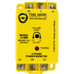
A158B
3-Phase MonitorSelect optionsThe Model 158 continuously monitors 3-phase power lines for abnormal conditions. When properly adjusted, the Model 158 monitor will detect phase loss on a loaded motor even when regenerated voltage is present.
This device consists of a solid-state voltage and phase-angle sensing circuit, driving an electro-mechanical relay. When correct voltage and phase rotation are applied, the internal relay will energize. A fault condition will de-energize the relay. When the fault is corrected, the monitor will automatically reset.
The Model 158 does not require a neutral connection, and can be used with Wye or Delta systems. Four versions cover 120V, 208/240V, 480V (60Hz) and 380V (50Hz). Voltage ranges are sufficient to allow for proper adjustment to existing conditions. A front-mounted LED failure indicator is provided.
The R versions of the Model 158 monitor have an additional LED indicator for RESTART and a 5 minute short cycle timer, to delay restarting the motor.
-
A158BR
3-Phase Monitor5 Min. Time DelaySelect optionsThe Model 158 continuously monitors 3-phase power lines for abnormal conditions. When properly adjusted, the Model 158 monitor will detect phase loss on a loaded motor even when regenerated voltage is present.
This device consists of a solid-state voltage and phase-angle sensing circuit, driving an electro-mechanical relay. When correct voltage and phase rotation are applied, the internal relay will energize. A fault condition will de-energize the relay. When the fault is corrected, the monitor will automatically reset.
The Model 158 does not require a neutral connection, and can be used with Wye or Delta systems. Four versions cover 120V, 208/240V, 480V (60Hz) and 380V (50Hz). Voltage ranges are sufficient to allow for proper adjustment to existing conditions. A front-mounted LED failure indicator is provided.
The R versions of the Model 158 monitor have an additional LED indicator for RESTART and a 5 minute short cycle timer, to delay restarting the motor.
-

A200
3-Phase Voltage Unbalance MonitorSelect optionsThe Model 200 3-Phase Voltage Unbalance Monitor is designed to continuously monitor a three-phase line for unbalanced voltage conditions.
This device will only energize the relay if an unbalance exists. Zero volts on all three phases is considered a balanced condition. This allows the Model 200 to be used with shunt breakers, so that the breaker can shut off the main power without tripping the monitor.
The solid-state sensing circuit drives an internal electromechanical relay. Indicator lights on the monitor show when the voltage balance is within an acceptable range; when an unbalance exists; and when the relay is actually tripped.
When an acceptable voltage balance is reapplied, the Model 200 will automatically reset the relay.
-
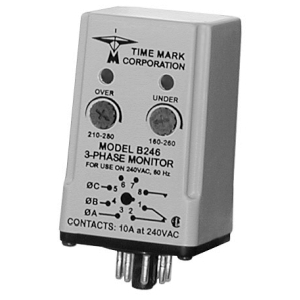
A246
3-Phase MonitorSelect optionsThe Model 246 3-Phase Monitor is designed to continuously monitor 3-phase power lines for abnormal conditions. This device features solid-state voltage and phase angle sensing circuits, which drive a SPDT electromechanical relay.
A neutral is not required, allowing the Model 246 to be used with either Wye or Delta systems.
Three versions of the Model 246 cover the 120 and 208/240 VAC, 60Hz and the 380 VAC, 50Hz ranges. In addition, the models A246 and B246 are now CSA Certified.
Each option on the Model 246 monitor is adjustable throughout its operating range. The adjustment pots and LED indicators of OVER VOLTAGE and UNDER VOLTAGE are mounted on the front of the unit, for easy access.
![]() Engineered and Built in the USA
Engineered and Built in the USA