4062

Time Mark

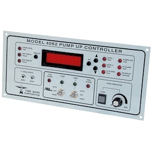
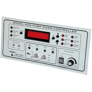
The Model 4062 Pump-Up Controller provides total control for duplex pumping systems. The Model 4062 monitors, controls and displays the liquid level in a tank or reservoir, up to a depth of 34.6 feet. The input to the Model 4062 can be from any 2 or 3-wire transducer with a 4-20mA output that represents 0 to 34.6 feet. A 24VDC regulated probe supply is included. A Level Simulator is provided to aid in programming these five set points; Low Alarm, Level 2, Level 1, Pumps Off and High Alarm. A universal zero to 30 second On Delay can be programmed to prevent outputs from closing due to input fluctuations caused by turbulent conditions. An additional 4-20mA output with zero and span controls is provided for a chart recorder or other external device. Four heavy-duty 10 amp, 120V contacts are provided for pump control and alarm activation. An auto-dialer or other emergency device can be activated with the SPDT power loss relay. This relay is held open when power is applied. Communications capable via RS-485/Modbus. Pump outputs include duplex alternation as well as hand-off-auto switches. Pump run-time can be displayed for each pump with tenth of an hour resolution, up to 99,999. 9 hours. The Model 4062 can be panel-mounted (11 1/8 x 4 5/8), same as Time Mark Models 403, 404, 4042 and 4052, or surface-mounted using the optional surface-mounting kit, Model 4000.

TMC430

Time Mark

The Time Mark model 430 pump controller is a versatile and advanced liquid level/pump management system. The Model 430 was designed to control up to three pumps with a 4-20mA input. It can also be used to control 2 pumps with a 4-20mA input and backup floats or to simply control two pumps with only float inputs. Alarm inputs are provided, if necessary, and may be disabled through the menu system if not used. Alarm inputs are: SF – seal fail, OT – over temperature, CF – contact failure, and SP – spare (eg. a second seal fail). A relay output is provided for the level alarm (either high or low), depending on pump configuration; PUMP UP or PUMP DOWN.

422

Time Mark

The Model 422 Submersible Pump Controller detects an overload or underload condition on all types of running pump motors: suction pumps, submersible pumps, etc. This Monitor detects the actual power used (voltage x current x power factor) and is more sensitive than simple current monitors. The 422 can be used with single phase pumps or, using the Model 276C current transducer, with 3-phase pumps. Matching CTs allow the Model 422 to be used with most pump motor sizes. Optional trip and restart delays are provided.

451

Time Mark

The Model 451 pressure transducer will convert 0-15psi to proportional 4-20mA signal. It can be used with any pump control system that utilizes a 4-20mA input for level control. The 451 can be mounted in a standard 8-pin octal socket for remote use.

662

Time Mark

The Model 662 Pump Up Control, part of the 600 series line of instrumentation controls, is designed to monitor andmaintain liquid levels. A user-provided 4-20mA current loop represents the liquid level, and output connections are provided for pump control. The HIGH ADJUSTsetpoint, and the LOW ADJUST setpoint, are field adjustable. If the input falls below the low setpoint, the PUMP UP relay energizes, and remains that way until the input rises above the high setpoint. The high setpoint must always be set above the low setpoint. Top-mounted LEDs on the Model 662 show system status. The PUMP UP LED turns ON when the input falls to 10% below the low setpoint, and resets when the input rises above this level. An INPUT LOOP ERROR LED turns ON if the input is outside the 4-20mA range. A Time Mark Model 650 Loop Power Supply (or equivalent) is required to provide the 24 VDC operating voltage.

A Time Mark Model 672-15 Pressure Transducer (or equivalent) is required to provide the input signal.

4052

Time Mark

The Model 4052 Pump-Down Controller provides total control for duplex pumping systems. The Model 4052 monitors, controls and displays the liquid level in a tank or reservoir, up to a depth of 34.6 feet. The input to the Model 4052 can be from any 2 or 3-wire transducer with a 4-20mA output that represents 0 to 34.6 feet. A 24VDC regulated probe supply is included. A Level Simulator is provided to aid in programming these five set points; Low Alarm, Pumps Off, Level 1, Level 2 and High Alarm. A universal zero to 30 second On Delay can be programmed to prevent outputs from closing due to input fluctuations caused by turbulent conditions. An additional 4-20mA output with zero and span controls is provided for a chart recorder or other external device. Four heavy-duty 10 amp, 120V contacts are provided for pump control and alarm activation. An auto-dialer or other emergency device can be activated with the SPDT power loss relay. This relay is held open when power is applied. Communications capable via RS-485/Modbus. Pump outputs include duplex alternation as well as hand-off-auto switches. Pump run-time can be displayed for each pump with tenth of an hour resolution, up to 99,999. 9 hours.

The Model 4052 can be panel-mounted (11 1/8 in. x 4 5/8 in.), same as Time Mark Models 403, 404 and 4042, or surface-mounted using the optional surface-mounting kit, Model 4000.

261-D-12

Time Mark

The Model 261 series Alternating Relay is designed for duplex pumping systems where it is desirable to equalize pump run time. The solid-state alternating circuit drives an internal electromechanical relay. A continuous power source and control switch are required. The control switch (float, pressure or other isolated contact) is connected between the L1 terminal and the control terminal. Each time the control switch is opened the output contacts will change states. Indicator lights on the case show the internal relay status. On the optional toggle switch versions, the toggle switch is set to the ALTERNATE position. Setting the switch to Load 1 or Load 2 will lock the relay in position, preventing alternation.

261-DT-12

Time Mark

The Model 261 series Alternating Relay is designed for duplex pumping systems where it is desirable to equalize pump run time. The solid-state alternating circuit drives an internal electromechanical relay. A continuous power source and control switch are required. The control switch (float, pressure or other isolated contact) is connected between the L1 terminal and the control terminal. Each time the control switch is opened the output contacts will change states. Indicator lights on the case show the internal relay status. On the optional toggle switch versions, the toggle switch is set to the ALTERNATE position. Setting the switch to Load 1 or Load 2 will lock the relay in position, preventing alternation.

261-DX-12

Time Mark

The Model 261 series Alternating Relay is designed for duplex pumping systems where it is desirable to equalize pump run time. The solid-state alternating circuit drives an internal electromechanical relay. A continuous power source and control switch are required. The control switch (float, pressure or other isolated contact) is connected between the L1 terminal and the control terminal. Each time the control switch is opened the output contacts will change states. Indicator lights on the case show the internal relay status. On the optional toggle switch versions, the toggle switch is set to the ALTERNATE position. Setting the switch to Load 1 or Load 2 will lock the relay in position, preventing alternation.

261-DXT-12

Time Mark

The Model 261 series Alternating Relay is designed for duplex pumping systems where it is desirable to equalize pump run time. The solid-state alternating circuit drives an internal electromechanical relay. A continuous power source and control switch are required. The control switch (float, pressure or other isolated contact) is connected between the L1 terminal and the control terminal. Each time the control switch is opened the output contacts will change states. Indicator lights on the case show the internal relay status. On the optional toggle switch versions, the toggle switch is set to the ALTERNATE position. Setting the switch to Load 1 or Load 2 will lock the relay in position, preventing alternation.