
Engineered and Built in the USA
(800) 862-2875

3-Phase-Monitors
Showing 97–112 of 213 resultsSorted by latest
-
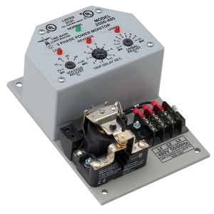
2500-208
The Model 2500 3-Phase Monitor is designed to continuously monitor 3-phase power lines for abnormal conditions. This device features solid-state voltage and phase-angle sensing circuits, which drive a SPDT electromechanical output relay.When the correct voltage and phase sequence is applied to a specified Model 2500, the output relay will not energize. An under voltage, phase reversal, phase unbalance or phase loss condition will cause the output relay to energize, even if regenerated voltage is present. Complete power loss will not cause Model 2500 to trip. The 2501 version of this unit operates in fail-safe mode, and the contacts de-energize on a fault condition. A neutral connection is not required, allowing the Model 2500 or 2501 to be used with either Wye or Delta system configurations.
Each option on the Model 2500 or 2501 monitor is adjustable throughout its operating range. The adjustment pots and LED indicators for VOLTAGE ADJUST, UNBALANCE ADJUST and TIME DELAY are mounted on the front of the unit for easy access.
Seven versions of the Model 2500 or 2501 cover voltage ranges from 120 to 600 VAC, and are UL Listed and CSA Certified.
-
2500-120
The Model 2500 3-Phase Monitor is designed to continuously monitor 3-phase power lines for abnormal conditions. This device features solid-state voltage and phase-angle sensing circuits, which drive a SPDT electromechanical output relay.When the correct voltage and phase sequence is applied to a specified Model 2500, the output relay will not energize. An under voltage, phase reversal, phase unbalance or phase loss condition will cause the output relay to energize, even if regenerated voltage is present. Complete power loss will not cause Model 2500 to trip. The 2501 version of this unit operates in fail-safe mode, and the contacts de-energize on a fault condition. A neutral connection is not required, allowing the Model 2500 or 2501 to be used with either Wye or Delta system configurations.
Each option on the Model 2500 or 2501 monitor is adjustable throughout its operating range. The adjustment pots and LED indicators for VOLTAGE ADJUST, UNBALANCE ADJUST and TIME DELAY are mounted on the front of the unit for easy access.
Seven versions of the Model 2500 or 2501 cover voltage ranges from 120 to 600 VAC, and are UL Listed and CSA Certified.
-
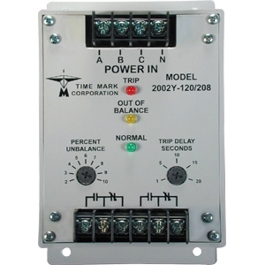
2002Y-69/120
The Model 2002Y 3-Phase Voltage Unbalance Monitor is designed to continuously monitor a three-phase line with a neutral connection for unbalanced voltage conditions.This device will only energize the relay if an unbalance exists. Zero volts on all three phases is considered a balanced condition. This allows the Model 2002Y to be used with shunt breakers, so that main power can be restored without resetting breakers.
The solid-state sensing circuit drives an internal electromechanical relay. Indicator lights on the monitor show when the voltage balance is within an acceptable range; when an unbalance exists; and when the relay is actually tripped.
-
2002Y-277/480
The Model 2002Y 3-Phase Voltage Unbalance Monitor is designed to continuously monitor a three-phase line with a neutral connection for unbalanced voltage conditions.This device will only energize the relay if an unbalance exists. Zero volts on all three phases is considered a balanced condition. This allows the Model 2002Y to be used with shunt breakers, so that main power can be restored without resetting breakers.
The solid-state sensing circuit drives an internal electromechanical relay. Indicator lights on the monitor show when the voltage balance is within an acceptable range, when an unbalance exists, and when the relay is actually tripped.
-
2002Y-240/415
The Model 2002Y 3-Phase Voltage Unbalance Monitor is designed to continuously monitor a three-phase line with a neutral connection for unbalanced voltage conditions.This device will only energize the relay if an unbalance exists. Zero volts on all three phases is considered a balanced condition. This allows the Model 2002Y to be used with shunt breakers, so that main power can be restored without resetting breakers.
The solid-state sensing circuit drives an internal electromechanical relay. Indicator lights on the monitor show when the voltage balance is within an acceptable range; when an unbalance exists; and when the relay is actually tripped.
-
2002Y-220/380
The Model 2002Y 3-Phase Voltage Unbalance Monitor is designed to continuously monitor a three-phase line with a neutral connection for unbalanced voltage conditions.This device will only energize the relay if an unbalance exists. Zero volts on all three phases is considered a balanced condition. This allows the Model 2002Y to be used with shunt breakers, so that main power can be restored without resetting breakers.
The solid-state sensing circuit drives an internal electromechanical relay. Indicator lights on the monitor show when the voltage balance is within an acceptable range; when an unbalance exists; and when the relay is actually tripped.
-
2002Y-138/240
The Model 2002Y 3-Phase Voltage Unbalance Monitor is designed to continuously monitor a three-phase line with a neutral connection for unbalanced voltage conditions.This device will only energize the relay if an unbalance exists. Zero volts on all three phases is considered a balanced condition. This allows the Model 2002Y to be used with shunt breakers, so that main power can be restored without resetting breakers.
The solid-state sensing circuit drives an internal electromechanical relay. Indicator lights on the monitor show when the voltage balance is within an acceptable range; when an unbalance exists; and when the relay is actually tripped.
-
2002Y-120/208
The Model 2002Y 3-Phase Voltage Unbalance Monitor is designed to continuously monitor a three-phase line with a neutral connection for unbalanced voltage conditions.This device will only energize the relay if an unbalance exists. Zero volts on all three phases is considered a balanced condition. This allows the Model 2002Y to be used with shunt breakers, so that main power can be restored without resetting breakers.
The solid-state sensing circuit drives an internal electromechanical relay. Indicator lights on the monitor show when the voltage balance is within an acceptable range, when an unbalance exists, and when the relay is actually tripped.
-
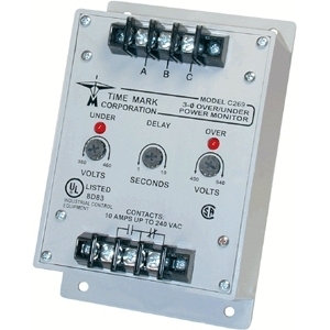
EX269
The Model 269 Over and Under 3-Phase Monitor continuously monitors 3-phase lines for high voltage, low voltage, phase loss or phase reversal. This device features a solid-state voltage and phase-angle sensing circuit, which drives a SPDT output relay.The Model 269 is independent of the system load, and may be used on any horsepower motor. When phase sequence is correct, and the voltage remains between the upper and lower trip points, the output relay remains energizes. When a fault condition is sensed, the output relay drops out.
The Model 269 does not require a neutral connection, and can be used on Wye or Delta systems. Each of the four voltage versions can be adjusted over a wide range. An adjustable trip delay (1-10 seconds) prevents nuisance tripping. OVER and UNDER voltage failure indicators aid in calibration and system troubleshooting.
-
C269
The Model 269 Over and Under 3-Phase Monitor continuously monitors 3-phase lines for high voltage, low voltage, phase loss or phase reversal. This device features a solid-state voltage and phase-angle sensing circuit, which drives a SPDT output relay.The Model 269 is independent of the system load, and may be used on any horsepower motor. When phase sequence is correct, and the voltage remains between the upper and lower trip points, the output relay remains energizes. When a fault condition is sensed, the output relay drops out.
The Model 269 does not require a neutral connection, and can be used on Wye or Delta systems. Each of the four voltage versions can be adjusted over a wide range. An adjustable trip delay (1-10 seconds) prevents nuisance tripping. OVER and UNDER voltage failure indicators aid in calibration and system troubleshooting.
-
B269
The Model 269 Over and Under 3-Phase Monitor continuously monitors 3-phase lines for high voltage, low voltage, phase loss or phase reversal. This device features a solid-state voltage and phase-angle sensing circuit, which drives a SPDT output relay.The Model 269 is independent of the system load, and may be used on any horsepower motor. When phase sequence is correct, and the voltage remains between the upper and lower trip points, the output relay remains energizes. When a fault condition is sensed, the output relay drops out.
The Model 269 does not require a neutral connection, and can be used on Wye or Delta systems. Each of the four voltage versions can be adjusted over a wide range. An adjustable trip delay (1-10 seconds) prevents nuisance tripping. OVER and UNDER voltage failure indicators aid in calibration and system troubleshooting.
-
A269
The Model 269 Over and Under 3-Phase Monitor continuously monitors 3-phase lines for high voltage, low voltage, phase loss or phase reversal. This device features a solid-state voltage and phase-angle sensing circuit, which drives a SPDT output relay.The Model 269 is independent of the system load, and may be used on any horsepower motor. When phase sequence is correct, and the voltage remains between the upper and lower trip points, the output relay remains energizes. When a fault condition is sensed, the output relay drops out.
The Model 269 does not require a neutral connection, and can be used on Wye or Delta systems. Each of the four voltage versions can be adjusted over a wide range. An adjustable trip delay (1-10 seconds) prevents nuisance tripping. OVER and UNDER voltage failure indicators aid in calibration and system troubleshooting.
-

EX265
The Model 265 3-Phase Monitor continuously monitors 3-phase Wye or Delta systems for phase loss, low voltage and phase reversal. When properly adjusted, the Model 265 Monitor will detect phase loss on a loaded motor even when regenerated voltage is present.The solid-state sensing circuit drives an internal relay, in a fail-safe configuration, i. e. , the relay is energized when correct voltage and phase rotation are applied.
Operating power for the Model 265 is drawn from the 3-phase lines being monitored. An adjustable timer delays restarting of the load, allowing up to five minutes for compressor head pressures to bleed off, in the event of short-term power failures.
The Model 265 Monitor is not sensitive to line current, and can be used with any size motor or compressor. Automatic and manual reset versions are available.
-
D265
The Model 265 3-Phase Monitor continuously monitors 3-phase Wye or Delta systems for phase loss, low voltage and phase reversal. When properly adjusted, the Model 265 Monitor will detect phase loss on a loaded motor even when regenerated voltage is present.The solid-state sensing circuit drives an internal relay, in a fail-safe configuration, i. e. , the relay is energized when correct voltage and phase rotation are applied.
Operating power for the Model 265 is drawn from the 3-phase lines being monitored. An adjustable timer delays restarting of the load, allowing up to five minutes for compressor head pressures to bleed off, in the event of short-term power failures.
The Model 265 Monitor is not sensitive to line current, and can be used with any size motor or compressor. Automatic and manual reset versions are available.
-
C265
The Model 265 3-Phase Monitor continuously monitors 3-phase Wye or Delta systems for phase loss, low voltage and phase reversal. When properly adjusted, the Model 265 Monitor will detect phase loss on a loaded motor even when regenerated voltage is present.The solid-state sensing circuit drives an internal relay, in a fail-safe configuration, i. e. , the relay is energized when correct voltage and phase rotation are applied.
Operating power for the Model 265 is drawn from the 3-phase lines being monitored. An adjustable timer delays restarting of the load, allowing up to five minutes for compressor head pressures to bleed off, in the event of short-term power failures.
The Model 265 Monitor is not sensitive to line current, and can be used with any size motor or compressor. Automatic and manual reset versions are available.
-
B265
The Model 265 3-Phase Monitor continuously monitors 3-phase Wye or Delta systems for phase loss, low voltage and phase reversal. When properly adjusted, the Model 265 Monitor will detect phase loss on a loaded motor even when regenerated voltage is present.The solid-state sensing circuit drives an internal relay, in a fail-safe configuration, i. e. , the relay is energized when correct voltage and phase rotation are applied.
Operating power for the Model 265 is drawn from the 3-phase lines being monitored. An adjustable timer delays restarting of the load, allowing up to five minutes for compressor head pressures to bleed off, in the event of short-term power failures.
The Model 265 Monitor is not sensitive to line current, and can be used with any size motor or compressor. Automatic and manual reset versions are available.