

120VAC
-
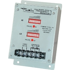
B292
The Model 292 Frequency Monitor is designed to monitor power line frequency. It is intended for systems where line frequency variations will cause improper operation of electrical equipment. A solid-state sensing circuit drives an internal electromechanical relay which is energized when the line frequency is correct. Operating power is drawn from the same line being monitored.The Model 292 is set to the over and/or under frequency trip points using ten binary-coded switches. A frequency variation outside the trip points causes the internal relay to drop out and an appropriate LED indicator to illuminate.
Applications for the Model 292 include stand-by power plants, portable power supplies, and windmill generators.
-
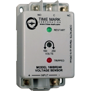
160BR120
The Model 160B(R) Voltage Sensor is a single set-point voltage sensor. Input voltages above the set-point cause the output contacts to energize. Input voltages below the set-point cause the output contacts to de-energize. The dead band between pull-in and drop-out is less than 1%.Wiring connections are made to 1/4 in.; quick connect terminals. Standard versions have a 2-second restart delay. The R versions of the Model 160B have a fixed 5-minute short cycle delay. The Model 160B has a screwdriver adjustable set-point range of approximately 35% of the maximum voltage. The unit can be factory calibrated to meet specific requirements.
AC versions of the Model 160B are not frequency sensitive and may be used in systems from 50 to 400 Hz. DC versions, or other short cycle periods, are available on request.
-
160B120
The Model 160B(R) Voltage Sensor is a single set-point voltage sensor. Input voltages above the set-point cause the output contacts to energize. Input voltages below the set-point cause the output contacts to de-energize. The dead band between pull-in and drop-out is less than 1%.Wiring connections are made to 1/4 in.; quick connect terminals. Standard versions have a 2-second restart delay. The R versions of the Model 160B have a fixed 5-minute short cycle delay. The Model 160B has a screwdriver adjustable set-point range of approximately 35% of the maximum voltage. The unit can be factory calibrated to meet specific requirements.
AC versions of the Model 160B are not frequency sensitive and may be used in systems from 50 to 400 Hz. DC versions, or other short cycle periods, are available on request.
-
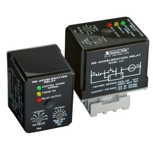
553-05
The Model 553-05 Re-Acceleration Relay is designed to take the place of a voltage sensing relay and two time delay relays. When voltage is applied to the Model 553-05, and the external start switch is closed, the adjustable on-delay time begins. After the delay period, the contacts will close. If the line voltage drops below 90 volts, the contacts open and the true-off delay begins. If the voltage rises above 102 volts before the true-off delay has elapsed, the contact will re-close. If voltage is not restored to 102 volts before the true-off delay time period ends, the contacts will remain open until the external start switch is closed. -
553-04
The Model 553-04 Re-Acceleration Relay is designed to take the place of a voltage sensing relay and two time delay relays. When voltage is applied to the Model 553-04, and the external start switch is closed, the adjustable on-delay time begins. After the delay period, the contacts will close. If the line voltage drops below 90 volts, the contacts open and the true-off delay begins. If the voltage rises above 102 volts before the true-off delay has elapsed, the contact will re-close. If voltage is not restored to 102 volts before the true-off delay time period ends, the contacts will remain open until the external start switch is closed. -
553-03
The Model 553-03 Re-Acceleration Relay is designed to take the place of a voltage sensing relay and two time delay relays. When voltage is applied to the Model 553-03, and the external start switch is closed, the adjustable on-delay time begins. After the delay period, the contacts will close. If the line voltage drops below 90 volts, the contacts open and the true-off delay begins. If the voltage rises above 102 volts before the true-off delay has elapsed, the contact will re-close. If voltage is not restored to 102 volts before the true-off delay time period ends, the contacts will remain open until the external start switch is closed. -
553-02
The Model 553-02 Re-Acceleration Relay is designed to take the place of a voltage sensing relay and two time delay relays. When voltage is applied to the Model 553-02, and the external start switch is closed, the adjustable on-delay time begins. After the delay period, the contacts will close. If the line voltage drops below 90 volts, the contacts open and the true-off delay begins. If the voltage rises above 102 volts before the true-off delay has elapsed, the contact will re-close. If voltage is not restored to 102 volts before the true-off delay time period ends, the contacts will remain open until the external start switch is closed. -
553-01
The Model 553-01 Re-Acceleration Relay is designed to take the place of a voltage sensing relay and two time delay relays. When voltage is applied to the Model 553-01, and the external start switch is closed, the adjustable on-delay time begins. After the delay period, the contacts will close. If the line voltage drops below 90 volts, the contacts open and the true-off delay begins. If the voltage rises above 105 volts before the true-off delay has elapsed, the contact will re-close. If voltage is not restored to 105 volts before the true-off delay time period ends, the contacts will remain open until the external start switch is closed. -
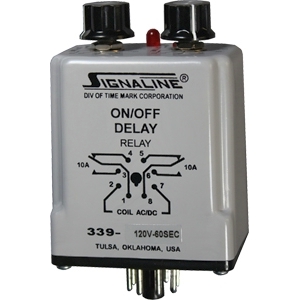
339-120-60
The Model 339 On/Off Delay Relay is an electronic time delay relay which provides two functions: on delay, and true off delay. The true off delay, (relay remains energized for a delay period when power is removed) is provided by means of an internal latching relay. Each time delay, on and off, is separately adjustable to a maximum of five minutes on or off. The Model 339 uses the same pin-out configuration as standard time delay and general purpose relays. It can be used in new or replacement applications for thermal, pneumatic, or spring-wound timers, or in place of general purpose relays or other electronic timers. -
339-120-300
The Model 339 On/Off Delay Relay is an electronic time delay relay which provides two functions: on delay, and true off delay. The true off delay, (relay remains energized for a delay period when power is removed) is provided by means of an internal latching relay. Each time delay, on and off, is separately adjustable to a maximum of five minutes on or off. The Model 339 uses the same pin-out configuration as standard time delay and general purpose relays. It can be used in new or replacement applications for thermal, pneumatic, or spring-wound timers, or in place of general purpose relays or other electronic timers. -
339-120-180
The Model 339 On/Off Delay Relay is an electronic time delay relay which provides two functions: on delay, and true off delay. The true off delay, (relay remains energized for a delay period when power is removed) is provided by means of an internal latching relay. Each time delay, on and off, is separately adjustable to a maximum of five minutes on or off. The Model 339 uses the same pin-out configuration as standard time delay and general purpose relays. It can be used in new or replacement applications for thermal, pneumatic, or spring-wound timers, or in place of general purpose relays or other electronic timers. -
339-120-10
The Model 339 On/Off Delay Relay is an electronic time delay relay which provides two functions: on delay, and true off delay. The true off delay, (relay remains energized for a delay period when power is removed) is provided by means of an internal latching relay. Each time delay, on and off, is separately adjustable to a maximum of five minutes on or off. The Model 339 uses the same pin-out configuration as standard time delay and general purpose relays. It can be used in new or replacement applications for thermal, pneumatic, or spring-wound timers, or in place of general purpose relays or other electronic timers. -
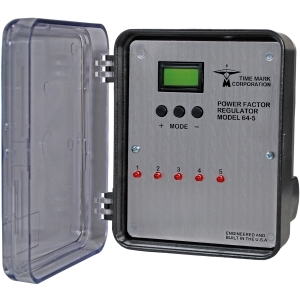
64-5
The Model 64-5 Power Factor Regulator is a monitoring and power factor control system. It is designed to help obtain an improved power factor, with a minimum of added capacitors. This device uses a unique phase-angle sensing circuit to monitor the power factor of a 3-phase power line. The Model 64-5 automatically responds to changing power factor by closing or opening the internal relays, which add or subtract capacitor banks on the line. Although intended for 115VAC 60Hz systems, other voltage or frequency models may be available. -
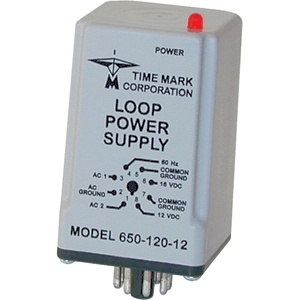
650-120-24
The Model 650 Loop Power Supply provides DC power for instrumentation control modules. Each option provides three output selections. For example the Model 650-240-24 has output options of 24 VDC regulated, 32 VDC unregulated, and 60 Hz pulse at 46 peak volts (See datasheet for all output selections).All outputs for the Model 650 are floating, electrically isolated from ground. A power status indicator (LED) is located on the top of the unit. The POWER LED comes ON when power is applied.
Applications for this device include two-wire current loop transducers, such as pressure, voltage or current. The Model 650 may also be used with alarm indicators, meters and timers.
-
650-120-12
The Model 650 Loop Power Supply provides DC power for instrumentation control modules. Each option provides three output selections. For example the Model 650-240-24 has output options of 24 VDC regulated, 32 VDC unregulated, and 60 Hz pulse at 46 peak volts (See datasheet for all output selections).All outputs for the Model 650 are floating, electrically isolated from ground. A power status indicator (LED) is located on the top of the unit. The POWER LED comes ON when power is applied.
Applications for this device include two-wire current loop transducers, such as pressure, voltage or current. The Model 650 may also be used with alarm indicators, meters and timers.
-
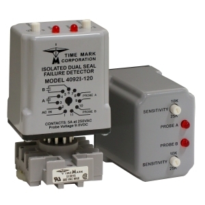
4092I-120
The Model 4092I Isolated Dual Seal Failure Detector is designed specifically for monitoring the shaft seals of two submersible pumps. All electrical inputs are totally isolated from each other. The probes are to be installed in the seal cavities of each of the pumps. The sensitivity is field adjustable. When a seal begins to leak, contaminating fluid enters the seal cavity, lowering the resistance between the probe and the common connection. If the resistance drops below the sensitivity set-point, the corresponding relay and the LED indicator are activated. The Model 4092I will automatically reset when the fault condition is corrected.Also available in a 240 VAC version, ask for details.